Anti-reflection (AR) thin film coatings are used to optimize desired wavelength(s) or broad spectrum of light transmissions and reduce unwanted surface reflections. AR coatings are the most widely specified coating used in both commercial and defense applications including imaging, solar, auto, semi, medical, life science, telecom, and electronics. The global AR coatings market size was estimated at USD 3.27 billion in 2015 and is expected to reach USD 7.50 billion by 2025, according to a report by Grand View Research.
In the traditional sense of visible broadband and single wavelength V-type coatings, materials, machines, and processes, coupled with increasing demand from existing and emerging applications such as lidar and AV/VR has led to an evolution in AR coating capabilities. While well defined, understanding the flexibility and range of AR coatings is critical. We will review some of the discussions around AR coatings and considerations for maximizing performance.
AR coatings and Glass Types
Anti-reflection coatings cover wavebands from the deep UV to far infrared. It is possible to create Anti-Reflection coatings that perform with very low reflection (<0.05%). In general, the broader the wavelength range specified, the less effective the coating in reducing reflection. One consideration for optical designers is choosing the correct glass type for your application.
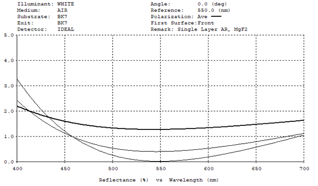
The coating curve below (figure 1) illustrates a single layer MgF2, centered at 550nm at normal incidence. The various curves chart different glass types with varying indexes of refraction. The dark top line is N-Bk7 substrate with Nd = 1.517. The middle line is SF5 with Nd = 1.673 and the lower SF57 substrate with Nd = 1.850. Optical designers take this into account along with application requirements and desired performance, when designing components for an optical system.
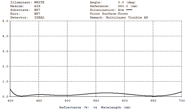
Applications requiring a multilayer broadband AR coating enhance transmission and cover a wider range of visible wavelengths. The coating in figure 2 is designed for low index glass types, in this case N-Bk7. Coatings can be modified to match other medium and higher index glass types with similar performance.
Bandwidth, Performance, and Cost
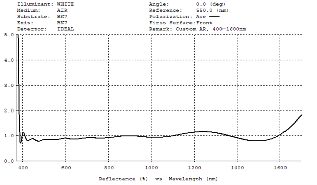
Generally, the higher the AR coating efficiency, the higher the cost. It is a trade-off between bandwidth, performance, and cost. For example, in Lidar applications operating at 905nm, it is possible to achieve R< 0.05% at 905nm with a bandwidth +/-5nm. It also theoretically possible to extend the range 800-1000nm and maintain R<0.05%. However, it becomes much more challenging to manufacture increasing cost. Designing for R<0.2% across this range may be a more cost-efficient solution. As a reasonable low-cost option, the most common visible coatings are specified at Ravg < 0.5%, over 400-700nm. Extended bandwidth options such as visible through Near Infra-Red to SWIR are also available. The theoretical best performance for coatings designed to cover 400nm to 1600nm, is about Ravg = 0.95%. Typically, coating providers will offer Ravg <1.5% to allow for manufacturing tolerances. Figure 3 illustrates a multilayer broadband AR coating at normal incidence over 400 – 1600nm. This specific coating is designed for low index glass types, in this case substrate is N-Bk7.
Custom AR coating Designs
If we take a similar example of 400 – 1600nm and look to target more specific ranges – such as visible and two popular laser wavelengths 1064nm and 1550nm – a coating can be custom designed and manufactured to meet Ravg < 0.75% visible and R<0.5% at 1064nm and at 1550nm. This is a better manufacturable solution than Ravg < 1.5% across the full spectral range. Coatings can be modified to match other medium and higher index glass types with similar performances.
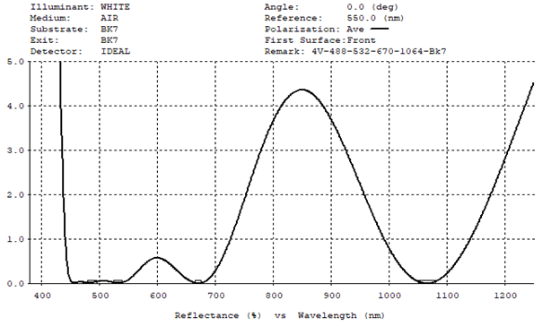
Custom designed coatings can be tailored to your specific performance requirements for around the same cost as more standard off the shelf coatings. Custom coatings include designs to reduce reflection at several “peak” specific wavelengths. The coating curve in figure 4 shows a coating designed to operate at low reflectance and at four different wavelengths: 488nm, 532nm, 670nm, and 1064nm.
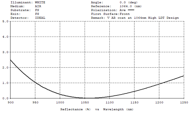
Commonly referred to as a “V” coating, figure 5 illustrates a design for high efficiency at a single wavelength. In this case the AR coating is designed to minimize reflection at 1064nm on fused silica and for a high laser damage threshold (LDT).
AR Coatings and Angles of Incidence
Light propagating normal to the substrate surface does not experience any polarization effects. As the angle of incidence (AOI) increases away from normal, the S (perpendicular) and P (parallel) planes of polarization become increasingly separated in both reflectance and transmittance. When designing a coating for 45deg AOI at random polarization, we are essentially trying to control two orthogonal rays with opposing properties.
For this reason, we typically specify coatings at higher AOI “less tight” than at normal incidence. Single wavelength AR coatings are commonly specified at R<0.2% at normal incidence, whereas at 45deg the common standard is R<0.5%, random polarization. This is not to say that R<0.2% or even R<0.1% cannot be achieved at higher angles. Thin film software algorithms can optimize low reflectance solutions at higher angles, but these designs are typically more challenging to manufacture and will come at a higher price.