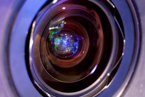
Beam-splitters are one of the most widely used components in optical systems. A Beam-splitter is an optical component that divides an incident beam of light into two or more beams by wavelength, polarization, or intensity. A portion of the beam is transmitted, while the other portion is reflected. Cube and plate Beam-splitters are two of the most used types and enable a variety of optically based products in the medical, biotech, laser, display, and test systems markets to name a few. The type and quality of the coating is critical to the performance of the beam-splitter in your application.
Ratio Beam-splitters
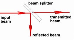
As the name suggests, the popular concept of a beam-splitter is to split a beam of light (or combine if used in reverse) into a predetermined ratio of Transmittance (T%) and Reflectance (R%). The most common beam-splitter is 50%T and 50%R, however, other ratios are also available. In most cases the reflected beam is directed at 90deg from the incoming beam, requiring the coating to function at 45deg angle of incidence (AOI).
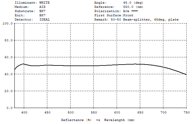
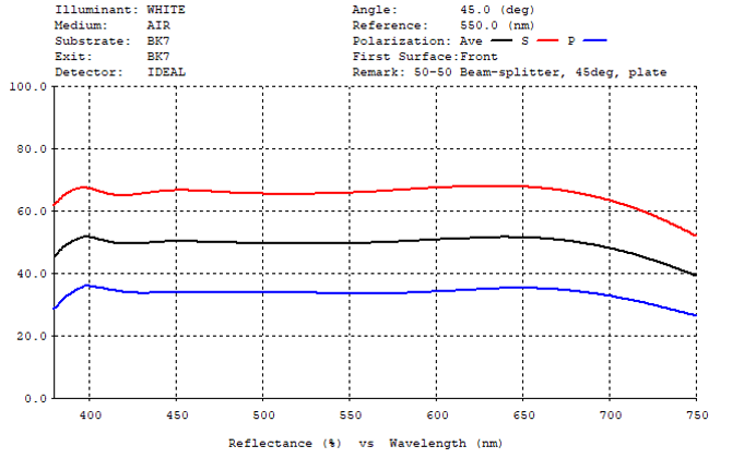
A 50T-50R beam-splitter designed for use at 45deg AOI across the visible spectrum (~400-700nm) is shown below. This coating is a 7-layer dielectric design. Note: for clarity, only the Reflectance condition is shown in these ‘ratio’ models.
In the above case we show the result for average polarization. If the optical system is sensitive to polarization bias, our design may need to take this into consideration. Here is the same beam-splitter including the performance of both P (parallel) and S (perpendicular) rays.
Ghost Imaging
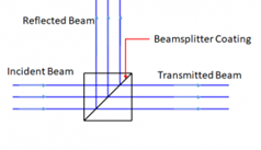
Another consideration is to apply an Anti-Reflecting (AR) coating on the back surface to avoid ghost imaging. Ghost imaging can also be avoided by using a cube beam-splitter. Cubes are preferred when the optical pathlengths of the split beams need to be equal or if the optical system cannot tolerate the displacement that occurs on the transmitted beam through the plate glass (refraction).
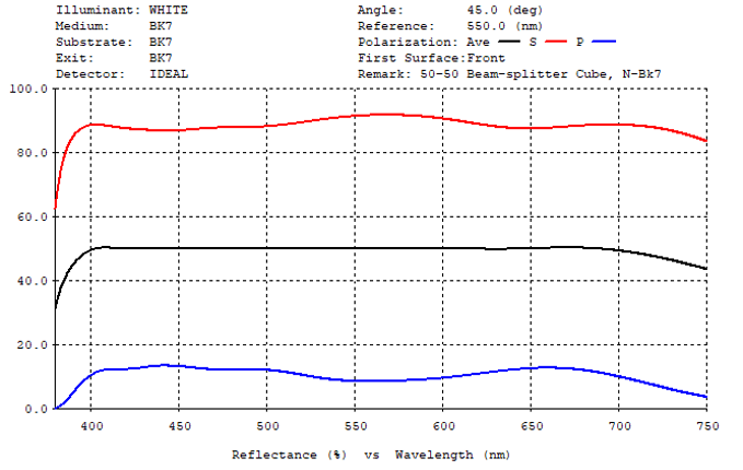
As can be seen in the above cube performance, the polarization splitting is more extreme in the cube than in the plate beam-splitter. By taking advantage of this condition, it is possible to make broad band polarizing cubes.
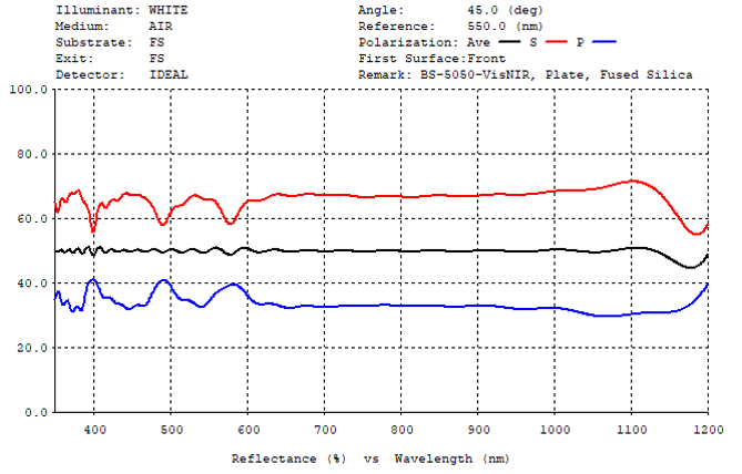
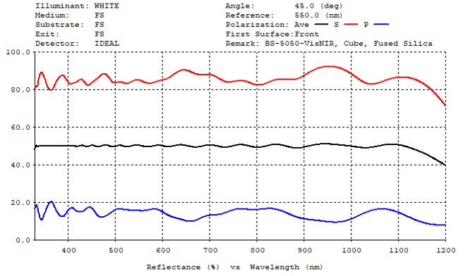
For examples of T:R ratio beam-splitters, the above compares 50:50 beam-splitters designed for an extended wavelength application 350-1100nm for both plate and cube. The plate design (top graph) is a 47 layer coating (Ta2O5/SiO2) and the cube design (lower graph) is a 41 layer coating (Ta2O5/SiO2). Although the cube BS requires fewer layers, the total physical thickness of the cube coating is 10% thicker than the plate coat. The key comparison is the polarization splitting. If your system is polarization sensitive, the preferred choice may be the Plate option. We discuss optical systems requiring very low polarization splitting in another article.
Color Separation Beam-splitters (Dichroic)
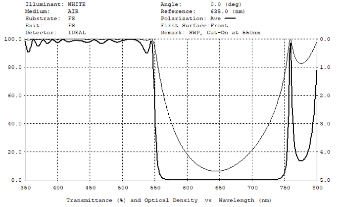
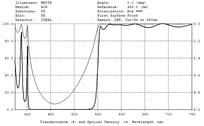
The term dichroic refers to the splitting of light into two colors. This is quite different from the R%, T% ratio previously discussed. Dichroic splitters are often referred to as Edge Filters and are normally Short Wave Pass type (SWP) or Long Wave Pass type (LWP). The SWP filter is designed to transmit shorter wavelengths and block the longer wavelengths. The LWP filter provides the opposite effect, transmitting longer wavelengths and blocking shorter.
Below are examples of both SWP and LWP filters. The dark line shows T% and the light line shows Optical Density which is a measure of the amount of light blocked by the filter. As the coating materials are essentially non-absorbing, the blocked light is reflected by the filter. Note: for clarity, only the Transmittance condition is shown in these dichroic models.
Optical Density
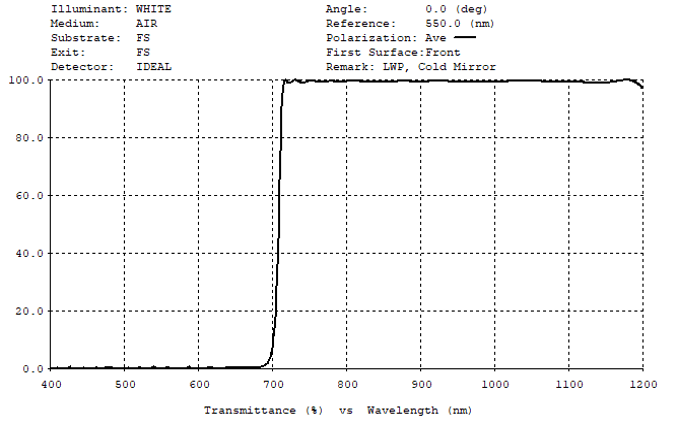
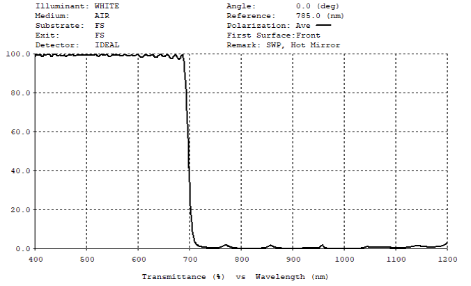
The Optical Density or blocking can be increased by adding more layers to the design where the added layers are similar to the layers in the original design. It is also possible to extend the blocking wavelength range of the SWP filter by adding thicker layers and by adding thinner layers to the LWP filter. If we design a LWP filter to block (reflect) the Visible wavelengths and transmit the wavelengths in the Near Infra-Red where heat is radiated then we have a LWP type ‘Cold Mirror’. Such coatings are used in dental and medical lighting where the mirrors reflect the intense light onto the patient while simultaneously transmitting the heat radiated from the lamp away from the patient. Alternately, by extending the blocking of the SWP filter to cover the Near Infra-Red range while transmitting the Visible range we can design a ‘Hot Mirror’.
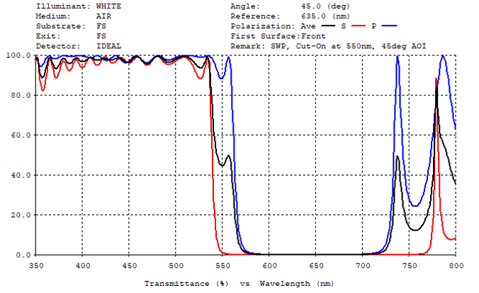
Dichroic Filters
Dichroic Filters can be designed to operate at 45deg AOI. In the example below a conventional SWP design (plate) is modified for 45deg incidence. As can be seen the S and P polarizations cut-on wavelengths differ at 45deg, compromising the sharp transition from blocking to transmitting. For many operations this is acceptable, however, this design will fail in applications such as Fluorescence Microscopy where a very sharp transition is often required to separate the excitation wavelength from the emission wavelength. In such cases more complex filters are needed to provide the necessary wavelength separation. These ‘Fluorescence’ type beam-splitters are covered in the next article “Polarization Control Coatings”.