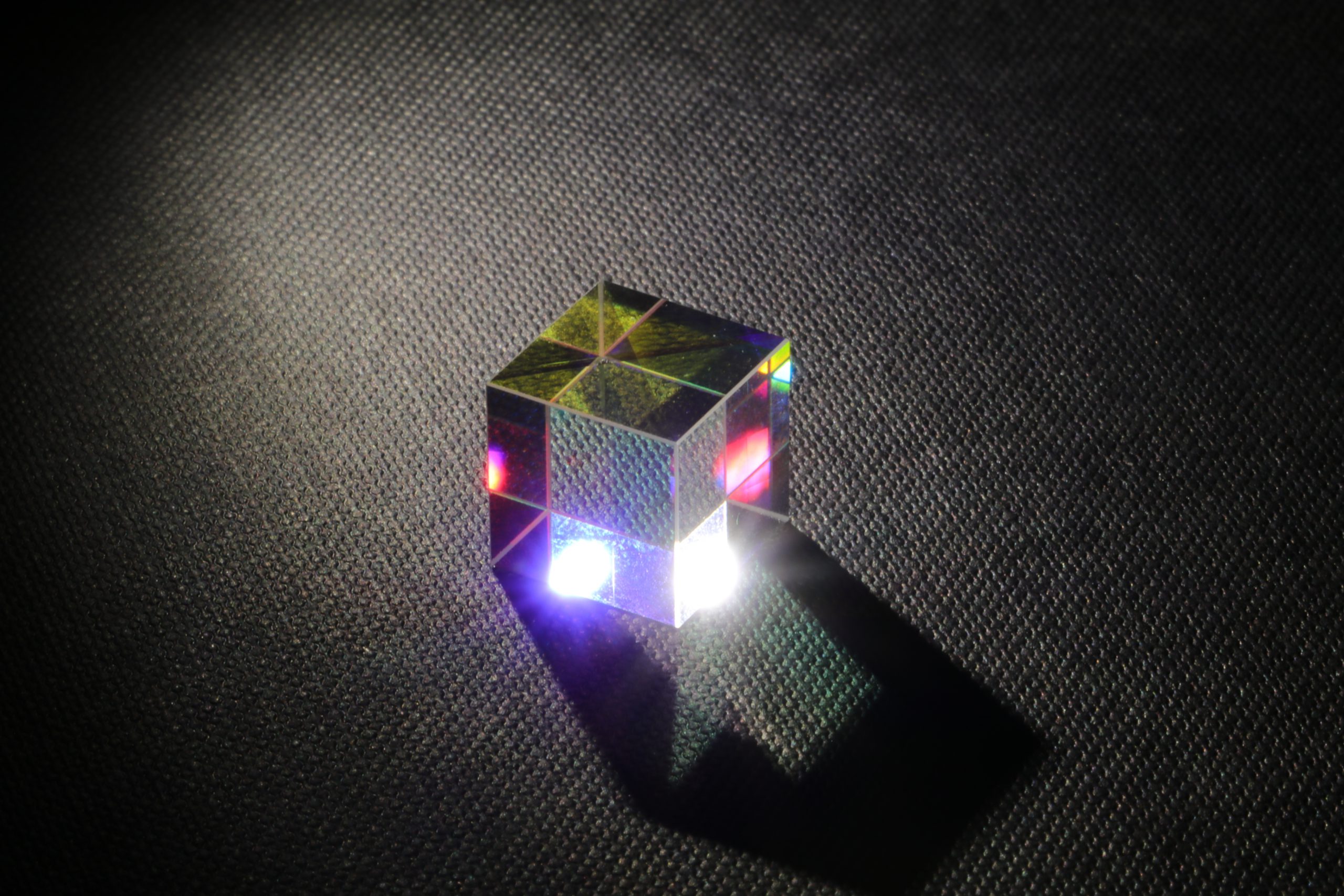
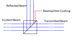
Beamsplitter coatings are normally produced on plate glass or in cube format. The incident beam splits into a partially transmitted beam and a partially reflected beam, where the reflected beam is typically directed 90 degrees from the Incident and transmitted beam. Figure 1 Here we discuss a special group of beam-splitters that use polarization and discuss the coatings designed to minimize polarization splitting.
Polarizing Coatings – Plate
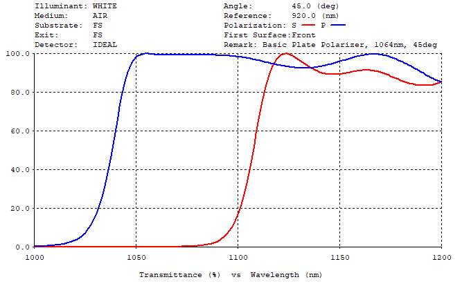
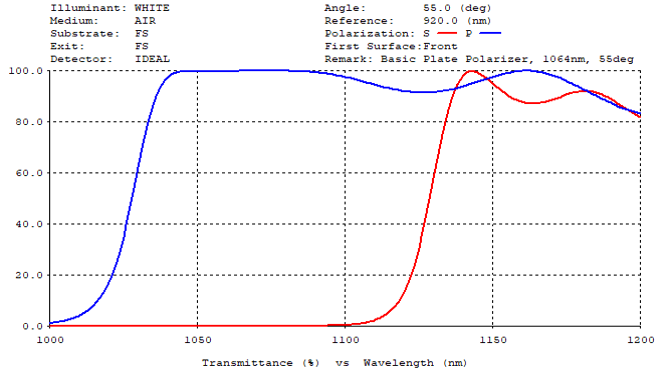
The most common polarizer is a single wavelength type. The basic design for a single wavelength 45deg plate polarizer has a relatively narrow range of wavelengths exhibiting polarization. The coating curve (figure 2) is a Long Wave Pass edge filter turned to 45deg and centered at 1064nm. If the coating is not accurately deposited the polarizing effect may occur at longer or shorter wavelengths than intended. If the accuracy varies from layer to layer, the overall efficiency of the polarizer may be compromised. Failure may also occur if the polarizer ‘drifts’ due to stability issues caused by changes in humidity or temperature. The polarizing bandwidth of this design can be expanded if the angle of incidence can be increased. Figure 3 is the basic design at 45deg AOI with the angle increased to 55deg AOI.
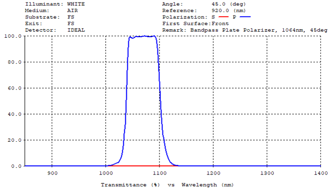
Staying with 45deg plates, an extended bandwidth polarizer can be designed by combining two plate type polarizers demonstrated in figure 4. This polarizer requires at least 2 times the number of layers compared with the basic design. This polarizer also acts as a bandpass polarizer, meaning the transmission occurs across a relatively narrow P Polarization band.
Polarizing Coatings – Cube
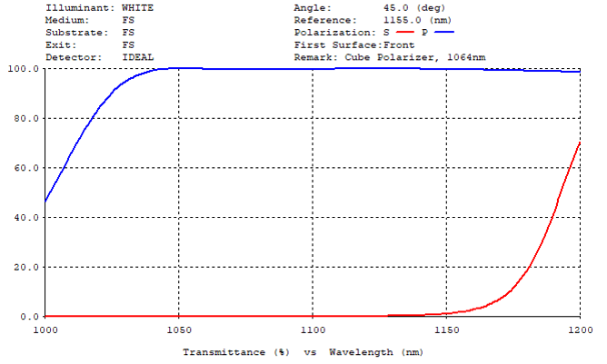
Due to increased polarization splitting in cube form, this type of single wavelength polarizer is most common. The design can produce a polarization ratio, Tp: Ts, also known as the Extinction Ratio, greater than 10,000:1 at the design wavelength. A cube polarizer protects the coating from environmental conditions like humidity since it is embedded in the cube and therefore the coating effectively does not ‘drift’. (Figure 5)
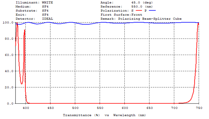
It is possible to take advantage of the polarization splitting within a cube to design broad band polarizers. In figure 6, Tp:Ts, the Extinction Ratio is > 500:1 at 410-700nm and > 10,000:1 at 425-685nm. Note that for these broadband Polarizers, the glass type is key to the performance. The refractive index of the glass must be a compatible match with the materials used in the coating design. In this case the coat materials are Ta2O5, SiO2 and the matching glass type is SF4 (Nd=1.755).
Non-Polarizing Coatings – Plate
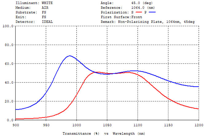
Single wavelength non-polarizing beamsplitters are possible in a glass plate. Figure 7 shows a 50:50 (T%:R%) where both polarization states P and S maintain the same 50:50 ratio.
Broadband Non-Polarizing Coatings
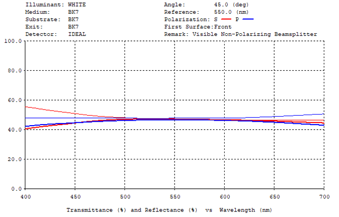
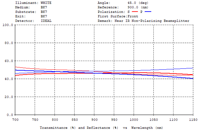
Due to the natural polarization splitting that occurs with dielectrics at higher angles of incidence, it is extremely difficult to design and manufacture a broad band non-polarizing coating using only dielectric materials. Instead, it is useful to include a metal layer, usually silver, along with dielectric layers to form a hybrid design. Refer to figures 8 and 9 (T% lines full color, R% lines lighter color). While these designs provide an acceptable level of non-polarization, the metal layer will introduce 5%-10% absorption. When designing a 50:50 ratio non polarizing coating the actual Ts,p% and Rs,p% is closer to 46%Ts:46%Tp:46%Rs:46%Rp. Also, due to the ‘soft’ and relatively reactive nature of silver, these coatings are best produced in cube form where they are protected from exposure to the environment and will continue to perform for many years.
Non-Polarizing Dichroic Beam-Splitters
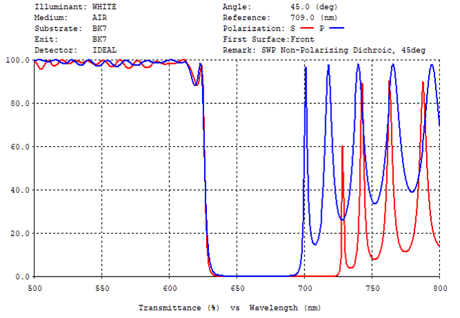
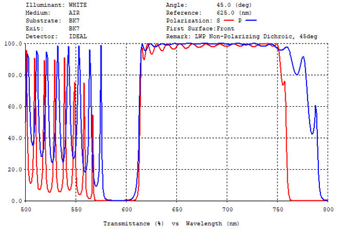
In Life-Sciences, many applications require 45deg beam-splitters with sharp transition from T% to R% to separate excitation from emission wavelengths. As shown above, standard design edge filters exhibit a polarization split when operating at 45deg. This polarizing effect produces a staggered cut-on that is unacceptable for sharp transition applications. To create a sharp transition, it may be necessary to use thin-film software with powerful optimization routines. The coating scans in figure 10 and 11, show LWP and SWP examples of these non-polarizing designs.
With many of these complex designs, tight tolerances are required in layer thickness accuracy and in homogeneity of the layer properties. To meet these challenges sputtering technology is often preferred over evaporation.